It is obvious that when two antennas are used in a communication system, they should be matched in polarization so that the available power at the receiving antenna can be fully utilized. A polarization match factor is developed and can be given in terms of the standard polarization parameters.
Effective Length of An Antenna
The transmitted field of any antenna can be written as:
where \(Z_0\) is the intrinsic impedance of free space, \(k\) is the free space propagation constant, \(\lambda\) is the wavelength, and \(I\) is an input current at an arbitrary pair of terminals. \(\mathbf{h}(\theta,\phi)\) is effective length of a general antenna. The effective length does not necessarily correspond to a physical length of the antenna. \(\mathbf{h}\) is a complex vector to describe an elliptical polarized field. With proper choice of coordinate system, \(\mathbf{E}^t\) and \(\mathbf{h}\) will have only two components since in the radiation zone \(\mathbf{E}^t\) has no radial component.
Received Voltage
The open-circuit voltage induced in a receiving antenna by an externally produced field is proportional to its effective length. The received voltage across the open terminals of the receiving antenna is:
where \(mathbf{h}\) is the effective length of the receiving antenna.
For maximum received power, the relationship between \(\mathbf{h}\) and \(\mathbf{E}^i\) is:
Polarization Match Factor
The polarization match factor is the ratio of actual power received to that received under the most favorable circumstances of matched polarization:
The polarization match factor is sometimes called polarization efficiency, and \(0\le\rho\le1\). The polarization match factor shows how well a receiving antenna of effective length h is matched in polarization to an incoming wave.
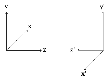
When two antennas are in transmit-receive configuration, both antennas will be described in its polarization properties by the right-handed coordinate system adjacent to itself. The following image shows the coordinate systems of two such antennas with opposite x-axis and z-axis. The reason is that antenna polarization is normally based on a right-handed system with z-axis pointing in the direction of outward wave from antenna.
The incident wave from antenna 1 may be written as:
The effective length of antenna 2 may be written as:
If the tilt angle of antenna 2 in the x'y'z'-system is \(\tau_2\), then it will be \(\pi-\tau_2\) in xyz-system.
Therefore, the induced voltage on antenna 2 is:
Also,
and
Then, the polarization match factor is:
\(\rho\) can be written in terms of \(q\) as:
It is not surprising that \(p\) has the same form in \(q\) as in \(p\), since the form for \(q\) in terms of \(p\) is the same as for \(p\) in terms of \(q\).
\(\rho\) can also be written in terms of axial ratio as:
where \(\beta=\tau_1+\tau_2\) is the angle between semi-major axes of the two elliptical polarizations.
Axial ratio does not provide the rotation sense information of the polarization. If axial ratio is purposely defined as positive for right-hand rotation and negative for left-hand rotation, then the formula can be used for cases with polarizations having either same or different rotation senses.
If inverse axial ratio \(\gamma=\frac{1}{AR}\) (\(0\le\gamma\le1\)) is used, then the polarization match factor can be written as:
Comments