Measuring the axial ratio (AR) of a circularly polarized antenna is important because it quantifies how close the antenna’s polarization is to ideal circular polarization, which directly affects signal quality, polarization matching, and system performance.
Measurement Method
A linearly polarized antenna is usually used to measure the axial ratio of a circularly polarized antenna. The method relies on the fact that a linearly polarized antenna responds differently to the major and minor axes of the polarization ellipse.
A circularly (or elliptically) polarized wave can be represented as two orthogonal linear components. When a linearly polarized probe is rotated about its boresight axis:
- The received power varies sinusoidally.
- The maximum received power corresponds to alignment with the major axis of the polarization ellipse.
- The minimum received power corresponds to alignment with the minor axis.
The axial ratio is then obtained from the ratio of these two field magnitudes.
Because received power is proportional to the square of the electric field:
In dB:
Polarization Purity Impact
When the linear polarization reference antenna has limited cross-polarization isolation (also called cross-pol discrimination or XPD), it will affect the accuracy of axial ratio measurements. The reference antenna's cross-polarization component introduces measurement errors that can make the circular polarization antenna appear better or worse than its actual performance.
Understanding the Error Mechanism
An ideal linear polarization antenna transmits only in its main polarization (e.g., vertical) with zero energy in the orthogonal polarization (e.g., horizontal). However, real antennas have finite cross-polarization isolation, meaning they transmit some unwanted energy in the orthogonal polarization.
When measuring a circular polarization antenna's axial ratio, the linear antenna's cross-polarization component adds to the measurement, corrupting the true polarization pattern. This is particularly problematic because circular polarization requires precise balance between orthogonal components.
Quantifying the Measurement Error
The polarization match factor between practical linear polarization and circular polarization antennas is (presented in Polarizations: Part3):
where
\(\rho(\phi)\) is a sinusoid of the form \(A+\sqrt{B^2+C^2}\cos (2\beta-2\beta_0)\), where \(\tan 2\beta_0=\tan 2\delta \cos\phi\), \(\gamma_{CP}=\tan \delta\). Therefore,
and,
The measured axial ratio is:
\(s\) is taken as \(+1\) with loss of generality.
For perfect linear polarization, \(\gamma_{LP}=0\), then \(AR_{meas}=\frac{1}{\gamma_{CP}}\), as expected.
For perfect circular polarization, \(\gamma_{CP}=1\), then \(AR_{meas}=1\), as expected too.
The true axial ratio is \(AR_{true}=\frac{1}{\gamma_{CP}}\). The measurement error in dB is:
The measurement error or uncertainty depends on the cross polarization phase difference (\(\phi\)) than the colinear polarization of the linearly polarized antenna. \(\phi\) is typically unknown and random.
Perfect Probe Case
If \(\phi=0^\circ, 180^\circ\), the formula reduces to \(\mathbf{AR}_{meas}=\frac{1}{\gamma_{CP}}=\mathbf{AR}_{true}\). For this case, both co-pol and cross-pol voltages scale together, and the measured AR is unaffected.
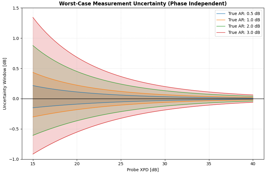
Worst-Case Error
The error is maximized when the \(\sin\phi\) and \(\cos 2\phi\) terms interact to minimize the denominator. This typically occurs near \(\phi = \pm 90^\circ\) (quadrature leakage). This gives \(\beta=0\) which means the major axis of the circular polarization is aligned with the linear polarization. The linear polarization is actually an elliptical polarization with major axis same as the colinear direction. \(\phi = \pm 90^\circ\) corresponds to the two rotation senses of the elliptical polarization that defines the two worst-case errors.
The measured axial ratio will be within the estimations of the two worst cases, as illustrated in the figure below.
Comments